Loop Antenna calculation and construction .
Calculation formula manual .
For my delta loop antennas , the formula :
30 M , center frequency 10.120 . λ loop = 1005 / 10.120 = 99,308 ft or λ
loop 306,3 / 10.120 = 30,02 m .
40 M , Center frequency 7,100 λ loop = 1005 / 7.100 = 141,55 ft or λ
loop 306,3 / 7.100 = 43,14 m .
The velocity factor of the antenne wire is not calculated with it in this formula !!!!
My delta loop antennas are not real triangles , the horizontal leg is longer and the side
legs shorter . The radiation diagram of my loop antennas change a bit .
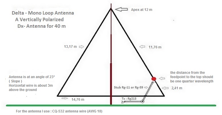
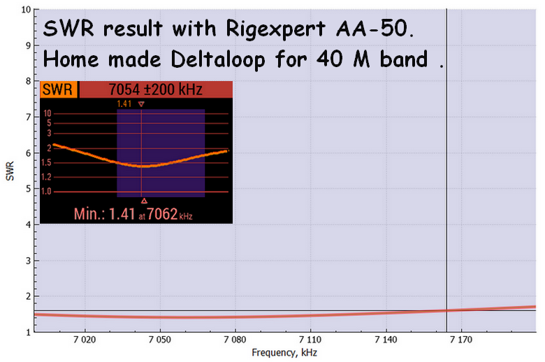
Delta Mono loop Antenna for 7 Mhz .
The feedpoint impedance of my full-wave loop is arround 100-120 Ohm with a gain over
a dipole of 1.35 dBi . The impedance changed depending on my configuration ,
orientation, and choice of feedpoint . To feeding this delta loop , I use 1/4 75 Ohm coax stub Rg-11
/ Rg-59 and later 50 Ohm coax to the transceiver .
Formula for the transformer : 75 Ohm X VF/Freq. , ( VF= velocity factor ) .
Using Rg-11A/U- Rg-59B/U Solid polyethylene ! ( VF = 0,66) as impedance transformer .
My calculation for 30 m : 75 x 0,66 / 10.120 = 4,89 m for 40 m : 75 X 0,66 /7.100 = 6,97 m .
Specification Rg-11A/U .
Specification Rg-59B/U .
I found the following powerhandeling for those coax cables depend on supplier.
| Power Handling Coax type / Vs Mhz . | 1.0 Mhz . | 10.0 Mhz . |
|---|---|---|
| Rg-11 | 8000 Watt | 2800 Watt |
| Rg-59 | 3900 Watt | 1100 Watt |
The feeding point is important , the distance from the feedpoint to the top should be one quarter
wavelength .
Whether this feeding point is left or right does not make a difference .
The antenna wire is CQ-532 (AWG 18) .
Using a 4:1 balun with a 50 Ohm coax to the transceiver is also a solution.
I use the delta loop on different qth's and every time I have to adjust the antenna .
| Dielectric Type . | Time Delay (ns/ft) . |
Propagation Velocity Factor . |
|---|---|---|
| Solid Polyethylene (PE) | 1.54 | 0.659c |
| Foam Polyethylene (FE) | 1.27 | 0.800c |
| Foam Polystyrene (FS) | 1.12 | 0.910c |
| Air Space Polyethylene (ASP) | 1.15-1.21 | 0.840c-0.880c |
| Solid Teflon (ST) | 1.46 | 0.694c |
| Air Space Teflon (AST) | 1.13-1.20 | 0.850c-0.900c |
Loop Calculator without velocity factor of the antenne wire .
With this calculator you calculate the lengths needed to construct
loop antennas . All you need to do is enter the desired
resonant (center) frequency in the form below, then click "Calculate Length".
The correct lengths for the loops models will be displayed in the
chart . This calculator is for HF antennas between 1.8 - 30 mHz .
I take always a bit longer length , better to long than to short !
Navigation
ON7YK
C5YK - C56YK - C5S
- Logbook

- C56YK Qth
- C56YK Dx Qsl Cards
- C5YK Qth till 2016
- C5YK Qth
- C5YK Dx Qsl Cards
- LoTW
- C5 - License
- ZD3 Op's till 1974
- C5 Op's 1975 till..
- E'Qsl
- 6M DXCC
- 6M EME setup
- 6M Beacons
- 6M Dx 2014
- 6M Dx 2015
Dx - Clusters
Links
Travelling
- Gambia Excursions
- Gambia Lodge
- Gambia Jan.2002
- Gambia Nov.2002
- Gambia Jan.2004
- Gambia Jan.2005
- Gambia Jan.2006
- Gambia Aug.2006
- Gambia 2014 +
- Austria Stubaital 2001
- Gambia-Belgium 2014
- North Cape 2014
- South-East Europe 2015
- Scandinavia 2016
- Scandinavia 2017
- North-East Europe 2018
- Baltic States 2019
- Sweden 2020
- Sweden 2021
- Sweden 2022
- Sweden 2023